
ChannelPlus 3015/3025 — Video Distribution System Manual
Installation and setup guide for the ChannelPlus (Linear LLC) Model 3015/3025 Video Distribution System, distributing 1-2 video sources plus antenna/cable signal to 4-5 TV locations.
Full text manual (for reference)
Installation and setup guide for the ChannelPlus (Linear LLC) Model 3015/3025 Video Distribution System, which distributes 1-2 video sources plus antenna/cable signal to 4-5 TV locations throughout a home. The 3025 (dual-input) can be upgraded for IR remote control from remote TV locations. This is a highly diagrammed manual; the wiring and programming figures below cover the key steps, with the full downloadable PDF containing the complete illustrated instructions.
Product Overview
- Model 3015: Accepts one video/audio input, creates one in-house TV channel; supports 4 TVs up to 150 ft of RG6 cable.
- Model 3025: Accepts two video/audio inputs, creates two in-house channels; supports 5 TVs (two at 35 ft max, three at 150 ft max).
- Both units amplify the antenna/cable input signal.
- Power Supply: Model 350-076, 15VDC, converts from 115VAC/60Hz.
- Not designed for outdoor use — requires a clean, dry installation location.
Materials Needed (Not Included)
- Coaxial cable (RG6): for connecting TVs to the base unit; RG59 usable but may reduce picture quality; "F" connectors required for bulk cable.
- Video (RCA) cables: yellow=video, red=right audio, black/white=left audio, needed to connect video source devices; typically sold in 3 or 6 ft lengths.
Installation Steps
- Verify existing TV/video equipment works correctly before installing.
- Determine your signal source:
- Cable: find two clear, non-adjacent unused channels (excluding 95-99) by tuning up from the last working channel.
- Antenna: scan channels 14-64 and note all clear/unused channels. Write these down — you'll need them for the programming step later.
- Choose an installation location for the base unit that is: close to video sources, close to the antenna/cable input, near a 110VAC outlet, and in a clean, dry environment.
- Mount the base unit using the provided screws (orientation is not critical).
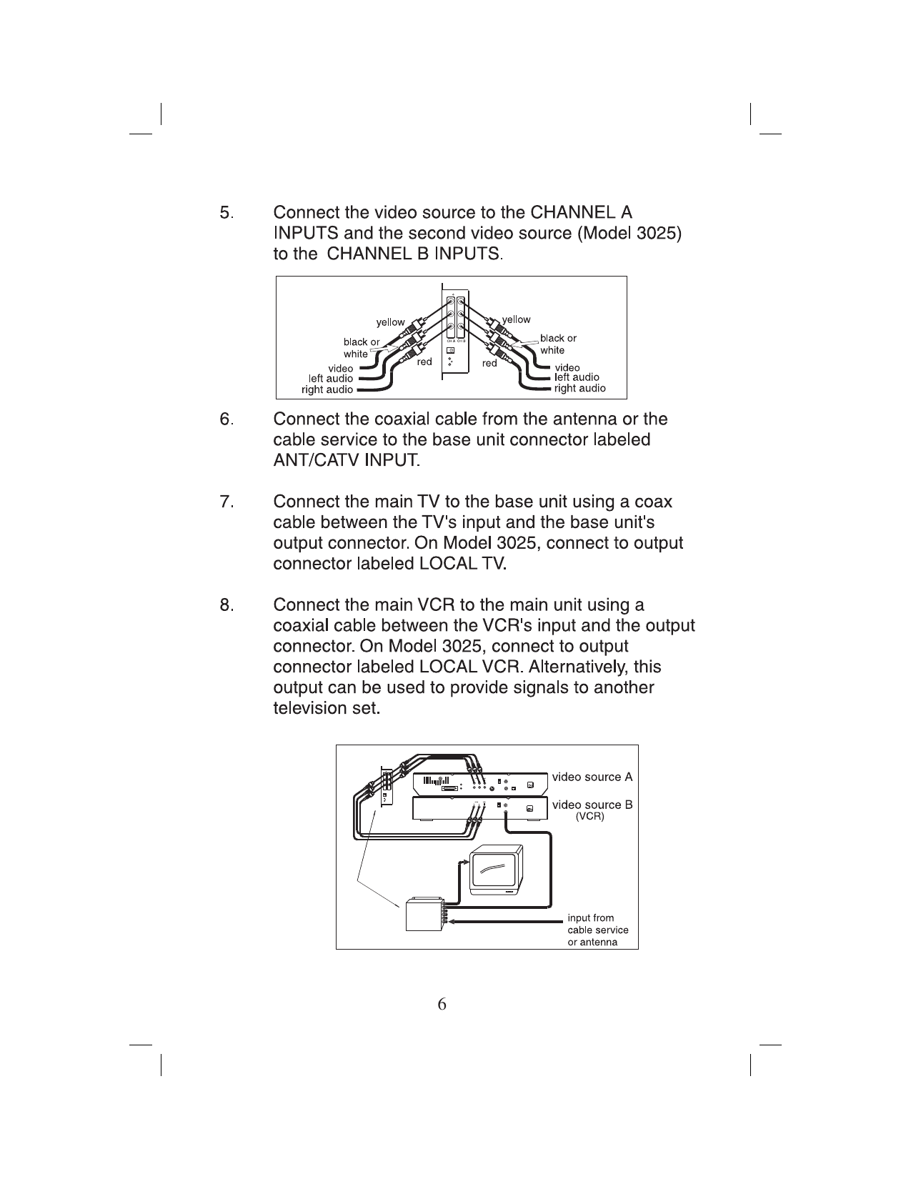
- Connect video sources via composite A/V cables (yellow=video, red=right audio, white=left audio) to CHANNEL A and CHANNEL B inputs.
- Connect the antenna/cable coax to the "ANT/CATV INPUT" jack.
- Connect the main TV and VCR via coax to the "LOCAL TV" and "LOCAL VCR" output jacks.
- Connect the power supply and confirm the green LED indicator is lit.
- Turn on the TV and determine whether you're in CATV or antenna mode.
- Select unused "in-house" channel numbers for Channel A and B, following the spacing rules noted above to avoid interference.
- Tune the TV to the selected channel and begin programming (see programming example below).
Wiring Diagram
Programming the Channel
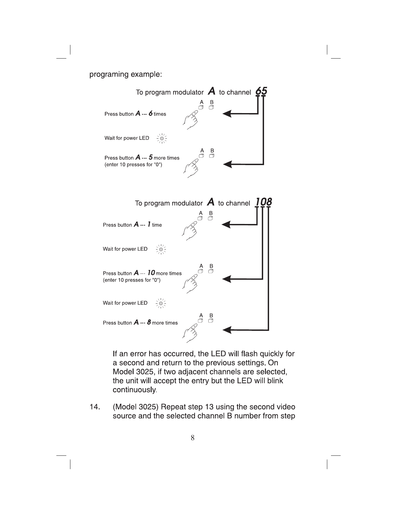
The unit is programmed by pressing a button labeled "A" (or "B") a specific number of times to enter a channel number, confirmed by an LED indicator.
- Example: To program Channel A to channel 65 — press the button 6 times, then 5 times.
- Example: To program Channel A to channel 108 — press the button 1 time, then 10 times, then 8 times.
- Rapid LED flashing indicates an error in the entry sequence.
- On the Model 3025, watch for channel conflict warnings between Channel A and Channel B assignments.
Readback Mode
Press and hold the programming button during power-up to make the LED blink out the currently programmed channel number (e.g., blinking 1-10-8 confirms channel 108 is set).
Cable HRC/IRC Frequency Standards
To reprogram the frequency assignment mode for special cable systems, enter channel 98 for HRC (Harmonically Related Carrier) or channel 99 for IRC (Incrementally Related Carrier).
Warranty
Linear LLC warrants this product to be free from defects in material and workmanship for 2 years from the date code on the product. The warranty is limited to repair or replacement of products returned freight-prepaid to Linear LLC — there is no provision for labor cost or other reimbursement. Not covered: damage from product abuse (negligence, improper use, electrical surge/lightning, water damage, natural disaster), tampering with date codes or labels, or shipping damage due to improper packaging. All warranty returns require a Return Product Authorization Number (RPA#) — contact Linear Technical Services at 1-800-421-1587.