
Channel Vision A0350 (Aria) — Flush Mount Amplifier Manual
Full instruction manual for the Channel Vision A0350 "Aria" Flush Mount Amplifier — connections, installation, wiring diagrams, and troubleshooting for 50W-per-channel in-wall amplification.
Full text manual (for reference)
Instruction manual for the Channel Vision A0350 "Aria" Flush Mount Amplifier — a 50-watt-per-channel Class D amplifier that installs behind a 2-gang box or inside a free-standing speaker cabinet, delivering powerful amplification for in-wall speakers or Channel Vision's SP525, SP650, and SP800 speakers.
Key Features
- 100-watt integrated Class D amplifier (50 watts per channel RMS)
- Pre-amp audio outputs for easy connection to a powered subwoofer
- Local audio input to override the wireless/CAT5 audio signal
- Compatible with Channel Vision's CAT5 audio systems
- Easy, low-profile installation — fits a standard 2-gang box
Front Panel Connections
- Power In: connect the power supply
- IR Input: connect an IR receiver (optional)
- Local Audio In: line-level audio sensing input that overrides the primary wireless or CAT5 audio
- Speaker Outputs: connect speakers directly
Rear Panel Connections
- Left & Right Audio Trim Pots: control the maximum output level of the amplifier (little noticeable effect on already-quiet input signals)
- Volume Jumper (J6): pins 1&2 = default power-up volume; pins 2&3 = resume previous volume on power-up (J7 not implemented)
- Rear Speaker Outputs: connect in-wall speakers
- RCA Outputs: connect to a powered subwoofer or external amplifier
- J17 & J18 Input Select Jumpers: set to pins 2&3 to select primary input from the CAT5 audio jack (pins 1&2 not implemented on the A0350). Note the front RCA inputs always function as a local source override regardless of jumper setting.
- CAT5 Audio Input: connect the output of your CAT5 audio hub here
- Keypad Input: connect an IR control keypad, such as the A0127
- 24VDC Power Input: rear screw terminals for remote power connection — follow polarity markings; don't use the front power connection at the same time
Installation
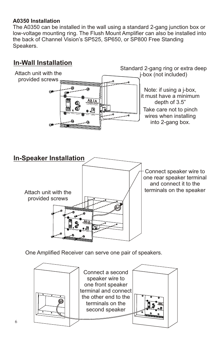
The A0350 installs in a standard 2-gang junction box or low-voltage mounting ring, or into the back of a Channel Vision SP525, SP650, or SP800 Free Standing Speaker.
- In-wall: attach with the provided screws into a standard 2-gang ring or extra-deep j-box (must have a minimum depth of 3.5"). Take care not to pinch wires during installation.
- In-speaker: attach with provided screws into the speaker cabinet; connect one rear speaker terminal to the first speaker, and one front speaker terminal to a second speaker — one A0350 can power one pair of speakers.
Common Setups
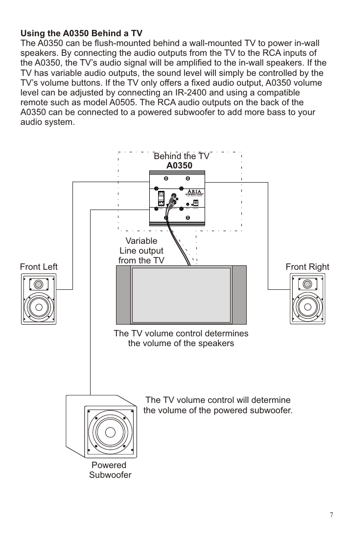
Behind a Wall-Mounted TV
Flush-mount the A0350 behind a wall-mounted TV and connect the TV's audio output to the A0350's RCA inputs to amplify the TV's sound to in-wall speakers. With a variable audio output, the TV's own volume buttons control speaker level; with a fixed audio output, use an IR-2400 receiver and a compatible remote (e.g. A0505) to control the A0350's volume. The rear RCA outputs can feed a powered subwoofer for added bass.
Stand-Alone System
Connect any audio source with a fixed or variable output directly to the A0350's RCA inputs to power in-wall speakers. Use an A0127 keypad, or an IR-2400 receiver with an A0505 remote, to control volume when the source has a fixed output.
With a CAT5 Audio Hub
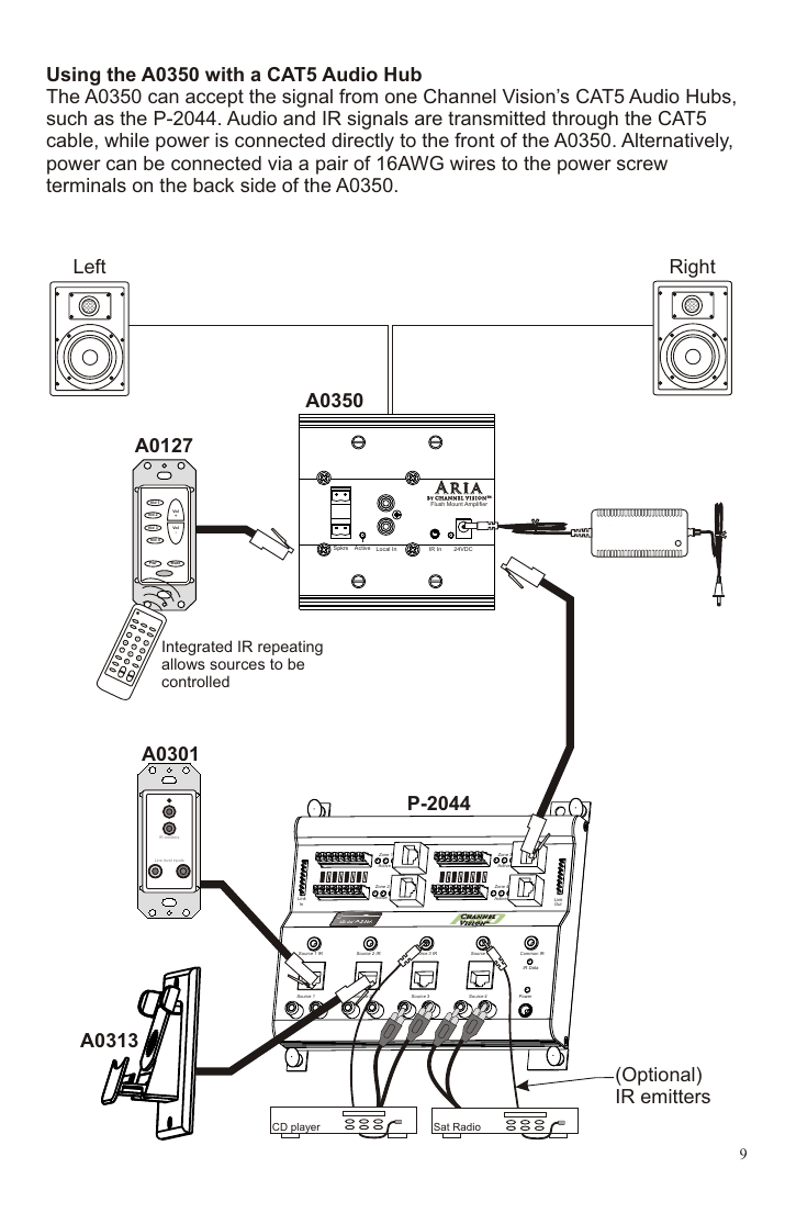
The A0350 can accept signal from a Channel Vision CAT5 Audio Hub such as the P-2044 — audio and IR signals travel over CAT5 cable while power connects directly at the A0350 (front) or via 16AWG wire to the rear screw terminals. An A0125 keypad and local input modules like the A0301/A0313 can be wired into the same CAT5 run for a full whole-house setup with integrated IR repeating.
Troubleshooting
| Problem | Cause | Solution |
|---|---|---|
| Hum in system | Components connected to different electrical grounds, causing a 60Hz hum from alternate ground current paths. | Plug all system components into the same outlet/circuit with a common ground. Try a ground-lifting plug. |
| CAT5 audio input not working | No/weak signal from the source; a source connected to the front RCA jacks is overriding the CAT5 input; jumpers J17/J18 set to the wrong pins. | Remove or turn off any source on the front RCA jacks. Set J17 and J18 to pins 1&2. Confirm the source audio is playing and the front-panel "Active" LED is lit. |
Specifications
- Power input: 24VDC
- Output power: 50 Watts/channel RMS into 6 ohms @ <10% THD
- Frequency Response: 20-20kHz (±3dB)
- Signal to Noise Ratio: >85dB
- Input Sensitivity: 500mVRMS
- Auto On Threshold: 10mVRMS
- Storage Temperature: -40 to +85°C
- Operating Temperature: 0 to +55°C
Related Accessories (sold separately)
- A0127: IR repeating keypad with volume codes for the A0350
- A0501, A0502, A0505: Remote controls with IR codes for the A0350 and other Channel Vision audio products
- IR-2400: Plasma-proof IR receiver
- Channel Vision in-wall, in-ceiling, and free-standing speakers
Warranty
Channel Vision Technology repairs or replaces defects in material or workmanship during normal use for one year from original purchase, free of charge in the USA, with new or rebuilt parts — a no-hassle warranty with no mail-in card required. Excludes shipping damage, third-party product failures, and damage from accident, misuse, abuse, or alteration. Extended only to the original purchaser; proof of purchase required for warranty repairs. Call (800) 840-0288 for mail-in service and a Return Authorization number.
Manufacturer: Channel Vision Technology, 234 Fischer Avenue, Costa Mesa, CA 92626 USA — (714) 424-6500 / (800) 840-0288 — techsupport@channelvision.com