
ABB-Welcome M2303 Guard Unit — User Manual
Complete user manual for the ABB-Welcome M2303 Guard Unit — a 4.3" touchscreen indoor station covering controls, menus, jumper settings, technical specs, and mounting/installation instructions.
Full text manual (for reference)
Overview
The ABB-Welcome M2303 Guard Unit is a 4.3" touchscreen indoor station for the ABB-Welcome door communication system. It functions as a monitoring/security station — handling incoming calls from outdoor stations and other indoor stations, surveillance of connected cameras, switch actuator control, and system-wide settings management. It must be installed only in dry indoor rooms and operates exclusively with other ABB-Welcome system components.
Warning — Electric voltage: Risk of death and fire from 100-240V. Work on the 100-240V supply system may only be performed by authorized electricians. Disconnect mains power prior to installation or disassembly. Low-voltage and 100-240V cables must never be installed together in the same flush-mounted socket.
Control Elements
| Control | Function |
|---|---|
| Handset | Pick up to activate communication within 30 seconds of an incoming call; hang up to end the call. |
| 4.3" Touchscreen | Primary interface for all menus and settings. |
| Unlock button | Opens the door at any time. Slow LED flash = incoming call; rapid flash = system busy or door held open past the set time (requires a connected sensor). |
| Surveillance button | In standby, press to view the default outdoor station's camera. |
| Programmable buttons 1–3 | Configurable for additional functions (e.g. switch actuator control). Button 1 defaults to releasing the lock connected to an outdoor station (COM-NC-NO). |
| System setting button | Enters system settings for device configuration. |
Start Screen Functions
The home/start screen provides quick access to: Intercept settings, Communication menu, Surveillance, Switch actuator menu, User list, History (events/alarms from indoor stations), Basic system settings (ringtone, volume, language), Advanced system settings (switch actuator setup, user list management), Date/time settings, plus status icons for cleaning-lock mode, new alarm history, new call history, and active intercept mode.
Key Menus & Settings
Contact / User List
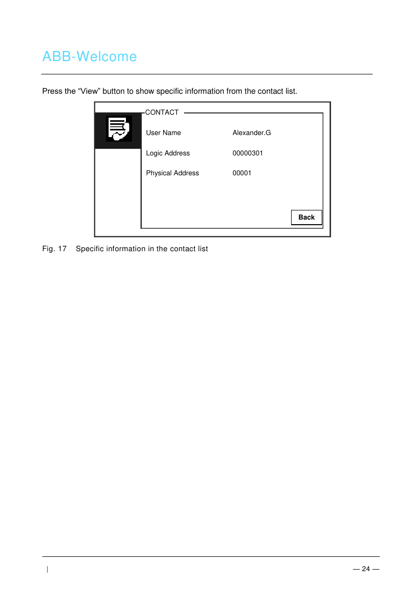
Displays contact details for each entry: User Name, Logic Address, and Physical Address — accessed by pressing "View" from the contact list. Up to a configurable number of users can be stored and managed here.
System Information
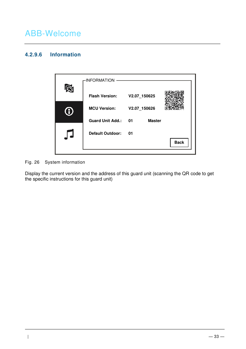
The Information screen shows Flash Version, MCU Version, the Guard Unit's own address, and the Default Outdoor unit number — plus a QR code linking to device-specific instructions. Useful for firmware verification and addressing checks during install/troubleshooting.
Advanced Settings Password
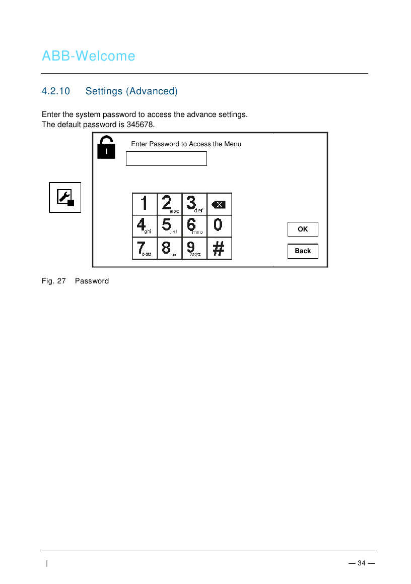
Advanced settings (switch actuator setup, user list management, call code, password, factory reset) are protected by a password. Default password: 345678. Change this after installation via Password Settings (enter a new 6-digit password, confirm, then OK).
Factory Reset
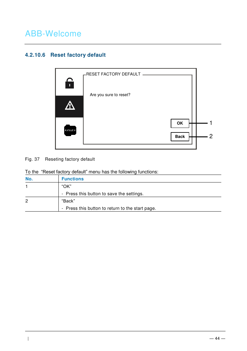
Reset Factory Default prompts "Are you sure to reset?" with OK/Back options. If the system password is forgotten, hold "0" while pressing "11411" within 120 seconds of power-on to enter Engineer Mode, from which you can reset the password or clear all data (switch actuator lists, user lists, history, etc.).
Adjusting the Device (Jumper Settings)
| Jumper | Function |
|---|---|
| Station | Sets the address of the default outdoor station. |
| X1 | Sets the address of the guard unit itself. |
| Master/Slave | Exactly one guard unit per building must be set "Master" (M/S on); all others must be "Slave" (M/S off). |
| Terminal resistor (RC) | In video or mixed audio/video installations, set RC on for the last device on the line. |
| a/b, DC/GND | a/b = bus connection, DC GND = additional power supply. |
| USB | Connects to a PC to upload/download configuration (e.g. contact lists). |
Technical Data
| Display resolution | 480 x 272 |
| Display size | 4.3" |
| Operating temperature | -10°C to +55°C |
| Storage temperature | -40°C to +70°C |
| Protection rating | IP 30 |
| Single/fine-wire clamps | 2 x 0.28 mm² – 2 x 0.75 mm² |
| Bus voltage | 20–30 V |
| Size | 144 x 198 x 45 mm |
Mounting / Installation
Requirements for the electrician: Install only with the necessary electrical engineering knowledge. Apply the "five safety rules" (DIN VDE 0105, EN 50110): disconnect from power, secure against reconnection, verify no voltage present, connect to earth, cover/barricade adjacent live parts. Use suitable protective clothing, tools, and measuring devices; verify the supply network type (TN/IT/TT).
General Installation Instructions
- Terminate all wiring branches via a connected bus device (indoor station, outdoor station, or system device).
- Do not install the system controller directly next to the bell transformer or other power supplies (interference risk).
- Never install system bus wires together with 100-240V wires.
- Do not share cables between door opener wiring and the system bus.
- Avoid bridges between different cable types.
- Use only two wires for the system bus, even within a four-core or multi-core cable.
- Never route incoming and outgoing bus loops inside the same cable, and never combine internal and external bus wiring in one cable.
Mounting Steps
- Fasten the device's bottom to the wall using the screw holes (per the dimension instructions in the manual), or to an existing flush-mounted box of compatible size.
- Wire the device per the terminal diagrams — insulated cable ends must not exceed 10mm.
- Set addresses for preferred outdoor/indoor stations via the jumpers (see Adjusting the Device above).
- Latch the upper housing onto the bottom part: align the top on the lock-in lugs, then press the bottom until it clicks into the retaining clamp.
- Available mounting options: wall-mount, existing flush-mounted box, or desktop bracket — all use the same latch-on assembly method.
Cleaning
Use only your finger or a plastic stylus on the touchscreen — hard or sharp objects can damage the screen surface. Clean with a soft cloth and commercial glass cleaner only; never use abrasive cleaning agents.