ABB-Welcome Lift Control Module (M2306/M2307) — Installation & Configuration Guide
Installation and configuration guide for the ABB-Welcome Lift Control Module system (M2306 adaptor + M2307 relay module) — restricts elevator access to authorized floors only.
Full text manual (for reference)
Installation and configuration guide for the ABB-Welcome Lift Control Module system — the M2306 adaptor and M2307 lift control relay module, which together restrict elevator access so residents and authorized visitors are automatically carried only to their designated floor.
Safety Warnings
- Electric voltage: Risk of death and fire from 100–240V supply. Work on the supply system may only be performed by authorized electricians. Disconnect mains power before installation or disassembly.
- Electric voltage (230V): Low-voltage and 230V cables must never be installed together in a flush-mounted socket — a short circuit could put a 230V load on the low-voltage line. The upstream fuse must be disconnected before working on the lighting system.
- Electrician requirements: Only install if you have the necessary electrical engineering knowledge. Incorrect installation endangers life and can cause serious property damage (e.g. fire). Apply the "five safety rules" (DIN VDE 0105 / EN 50110): disconnect power, secure against reconnection, verify no voltage, connect to earth, cover/barricade adjacent live parts. Use suitable PPE, tools, and measuring devices, and confirm the supply network type (TN/IT/TT) for correct grounding/earthing.
Environmental note: Used electric/electronic devices must not go into domestic waste — dispose of at an authorized collecting depot for recycling of valuable raw materials. ABB products comply with EU-Directive 2002/96/EG (WEEE), 2002/95/EG (RoHS), and the EU-REACH ordinance.
Function
The M2306 adaptor and M2307 lift control relay module work together to restrict elevator access to authorized floors only. When a resident presses the "unlock" button on receiving a call from the outdoor station, or an authorized user swipes a registered card / enters the correct password, the lift automatically travels to the floor where the outdoor station is installed, then carries the resident to their dedicated floor — floor buttons for other floors inside the lift cabin are disabled. Configuration is done via dedicated PC software connected to the M adaptor.
Technical Data
| Spec | Value |
|---|---|
| Single-wire clamps | 2 x 0.28–0.75 mm² |
| Fine-wire clamps | 2 x 0.28–0.75 mm² |
| Bus voltage | 20–30 VDC |
| Size (module) | 4 TE |
| Protection rating | IP20 |
| Operating temperature | -25°C to +55°C |
| Physical size — M2306 | 90 x 72 x 65 mm |
| Physical size — M2307 | 216 x 110 x 45 mm |
Connections
M2306
1) Status LED (ON = connected to system controller/internal bus; OFF = not connected; blinking = working). 2) Power indicator (ON = power on; OFF = power off; blinking = working). 3) Connection to M2307. 4) Power supply input. 5) Connection to the system controller / internal bus.
M2307
1) Power LED (ON/OFF for power state). 2) Setting LED (blinks during normal operation). 3) Address dial — sets the module address, range 1–16 (only the left 4 bits used). 4) Power supply input. 5) Connection to M2306. 6) Connection to the lift controller.
Mounting
The device must be installed on DIN EN 50022 mounting rails. The M2306 is recommended for installation in the lift motor room on the top floor, or the electrical riser. The M2307 is recommended for installation in the lift cabin itself.
Installation Topologies
The system scales from a single lift up to four lifts per building, depending on floor count:
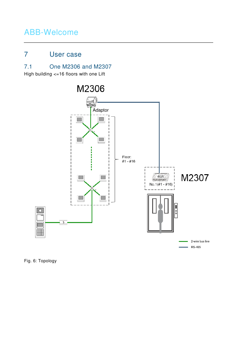
- One M2306 + one M2307 — supports buildings with ≤16 floors and one lift.
- One M2306 + one M2307 (extended) — supports buildings with >16 floors and one lift. The first mini system controller (M2301) feeds the M2306 and one M2307; any additional M2307 must be locally powered by its own mini system controller (e.g. 4 x M2307 + 1 x M2306 requires 4 mini system controllers total).
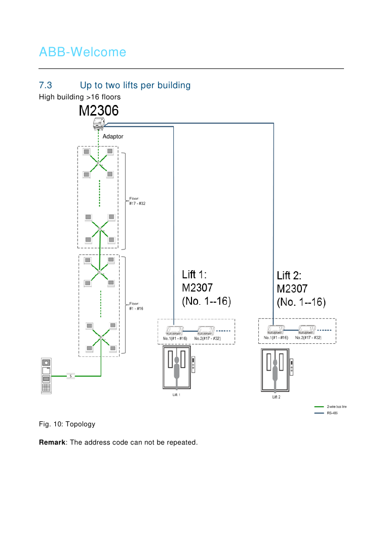
- Two lifts per building — for buildings >16 floors, one M2306 connects to two M2307 lift controllers, each assigned a distinct floor range. Address codes cannot be repeated across modules.
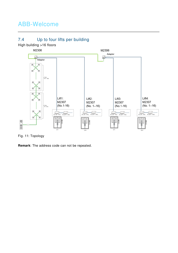
- Up to four lifts per building — two M2306 adaptors connect to four M2307 lift controllers for larger buildings. Address codes cannot be repeated.
Operation
Visitor scenario: When a resident presses "unlock" to admit a visitor calling from the outdoor station, the lift automatically travels to the outdoor station's floor for pickup, then proceeds to the resident's dedicated floor.
Resident scenario: Authorized residents (via registered card or password) are similarly restricted to their assigned floor when using the controlled lift.
Important: The lift control module will not activate when the unlock button is pressed without an incoming call from a building outdoor station — e.g., unlocking from a villa/floor outdoor station or gate station alone does not trigger lift dispatch.
Configuration via PC Software (ABB Welcome M PC Configuration Tool, Windows only)
During configuration, the M adaptor connects directly to a PC — no local power supply is required at that stage. After configuring, click "Send the Configuration" to upload the settings to the system.
- Set basic apartment parameters: select Building No., Floor No., and Apartment No.; set the Physical Address (from IS switches); set the User Name; set the Logic Address (e.g. 0703 = floor 07, apartment 03); click "Add" to add the apartment to the project; then upload the configuration.
- Configure each M2307 relay: select the Building No. and M2307 No. (click "Add" for a new M2307); set the relay connection to ON/OFF; choose output type NO or NC; set relay operation time (1–3600 seconds). Complete Steps 2–5 in order for each building before starting a new building.
-
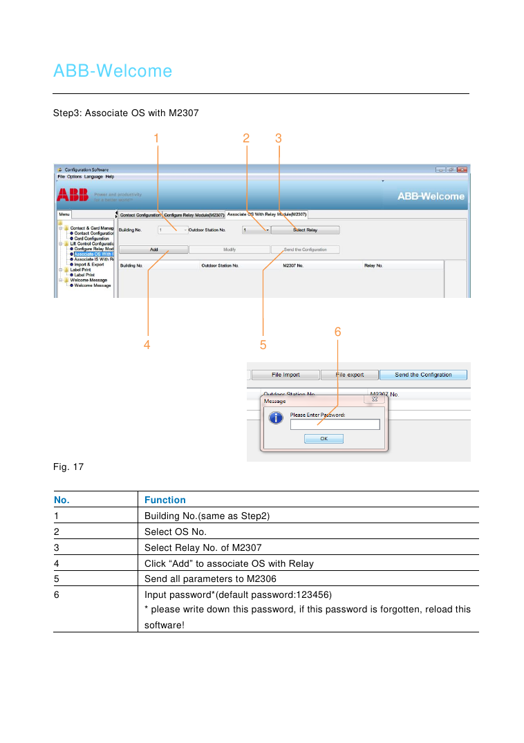
Associate the Outdoor Station (OS) with an M2307 relay: select Building No., OS No., and Relay No.; click "Add" to associate; send all parameters to the M2306; enter the password (default:
123456— write it down, as forgetting it requires reloading the software). - Associate the Indoor Station (IS) with an M2307 relay: select Building No., IS Physical Address, Relay No., and OS No. (the floor where that OS is installed); click "Add" to associate; send parameters to the M2306; enter the password.
- (Optional) Export/Import project data: export all Lift Control Configuration data to a read-only .xls file for future reference (recommended after each building's configuration is sent), or import data from an .xls file for a new project.
- Save as a new project: saves all configuration as an .xml project file.
- Open an existing project: load a saved .xml project to apply to a new OS, Guard Unit, and Lift Control setup.